Microsoft Dynamics AX 2012 Manufacturing – Lean Ninja IoT Scenario Part 5: Hardware/Software/Drivers
Purpose: The purpose of this document is to illustrate how to automate an advanced Make to Order Lean Manufacturing scenario in Microsoft Dynamics AX 2012 using IoT device.
Challenge: Microsoft Dynamics AX 2012 out-of-the-box enables mixed mode manufacturing including discrete, process, project and Lean approaches. Microsoft Dynamics AX 2012 R3 also offers advanced Warehouse management and Transportation management capabilities Manufacturers can greatly benefit from. In the previous part we've identified a need to introduce greater degree of variability into the scenario, specifically, around handling different quantities and handling different products. And now the goal is to dig deeper into a developer experience and implement all necessary software components required for advanced Lean Ninja IoT Demo scenario.
Solution: From the development perspective we are going to use Visual Studio (2015) to develop Headless Background App running on Raspberry Pi under Windows 10 IoT Core OS which will communicate with Microsoft Dynamics AX 2012 R3 backend. In order to implement requirements around handling different quantities and handling different products we are going to need a new set of sensors, in particular, load cell (a la electronic scale) and weight sensor (analogue-to-digital signal converter), and RFID sensor with antenna. To make use of these new sensors we'll implement appropriate drivers.
Please find complete reference to functional scenario being implemented here by going to the link: http://ax2012manufacturing.blogspot.com/2015/10/microsoft-dynamics-ax-2012_9.html
Walkthrough
Before we begin our deep dive into hardware and software parts I'll quickly refresh your memory on a functionality we are trying to automate in this scenario.
In the context of Lean Manufacturing workcell worker will perform assembly task at the designated workcell and will require a particular part. Water spider will be responsible to timely supply this part to workcell worker. The process will be controlled by kanbans, process and transfer kanban jobs will be assigned to workcell worker and water spider respectively. In addition to this warehouse management processes will be used to replenish Near Side Line location with parts from Warehouse bulk location, this will be done by Warehouse worker on hand-held device. In this scenario we will automate kanban replenishment process using industrial IoT device. Specifically water spider will refill emptied part location from main storage location for workcell worker to be solely focused on assembly task. Raspberry Pi IoT device powered by Windows 10 IoT Core will be used to automatically determine when part location should be replenished and send signals for kanban jobs assignments and updates
Here's the conceptual diagram of the process
Diagram
<![if !vml]> <![endif]>
 <![endif]>
Diagram – WMS point of view
<![if !vml]> <![endif]>
 <![endif]>
Diagram – Lean manufacturing point of view
<![if !vml]> <![endif]>
 <![endif]>
Section: Handling different quantities
In order to handle different quantities we will use load cell and weight sensor. Load cell will essentially be a special shape piece of aluminum alloy with wires and we will be able to measure analogue signal from it. In order to convert this analogue signal into digital signal we are going to need a weight sensor.
This is what we are going to use specifically in this experiment
Weight sensor: http://www.amazon.com/gp/product/B00NPZ4CPG

Load cell: http://www.amazon.com/gp/product/B00D0U6DXU

Principle
In this experiment I'll use so called "single point load cell" as depicted above. Its working principle is that when you fix one side and apply a force on another side load cell will undergo a deformation process causing a difference in voltages which we can measure and ultimately make a decision about weight put on the "scale".
Please see diagrams below for more details
Conceptual principle
|
Physical setup
|
 |  |
Weight sensor HX711 is a precision 24-bit analog-to-digital converter (ADC) designed for weigh scales and industrial control applications to interface directly with a bridge sensor.
Pin SCK and DT are used for data retrieval, input selection, gain selection and power down controls. When output data is not ready for retrieval, digital output pin DT is high. Serial clock input SCK should be low. When DT goes to low, it indicates data is ready for retrieval. Input and gain selection is controlled by the number of the input SCK pulse.
Table (gain values)

Setting up gain factor allows to convert number of impulses into a weight.
This is how impulses measured by weight sensor look like when applying weight on a load cell
Diagram

SCK (PD_SCK): Serial Clock Input
DT (DOUT): Serial Data Output
|
Weight sensor has multiple internal registers. Please note that no programming is needed for the internal registers. All controls to the HX711 are through the pins.
Please see my physical setup using load cell and weight sensor on the picture below
Picture

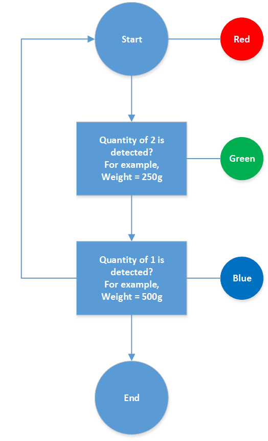
In order to better visualize the results I also introduced LED which lights up with different colors depending on weight applied on a load cell. Please see the diagram below for more details
Diagram (Handling different quantities)
<![if !vml]> <![endif]>
 <![endif]>
In my experiment I didn't convert number of impulses into a weight, instead for simplicity I determined experimentally a number of impulses which corresponds to a particular quantity. For example, average 5 impulses correspond to quantity of 2, 6 – to quantity of 1 and 7 – to none. Also to avoid fluctuation errors I introduced ranges within which measurements may vary: ( ; 5.5) |- Qty = 2; [5.5; 6.5) |- Qty = 1; [6.5; ) |- Qty = 0.
Source code
using System;
using System.Collections.Generic;
using System.Linq;
using System.Text;
using System.Net.Http;
using Windows.ApplicationModel.Background;
using Windows.Devices.Gpio;
using Windows.System.Threading;
using System.Diagnostics;
using System.Threading.Tasks;
namespace AlexBackgroundApplication
{
public sealed class StartupTask : IBackgroundTask
{
BackgroundTaskDeferral deferral;
private GpioPin pinR, pinG, pinB;
private GpioPin pinDT, pinSCK;
public void Run(IBackgroundTaskInstance taskInstance)
{
deferral = taskInstance.GetDeferral();
InitGPIO();
}
private void InitGPIO()
{
DateTime startTimeDelay = DateTime.Now, endTimeDelay;
double elapsedMillisecsDelay;
int[] data = new int[3];
double result = 0;
pinDT = GpioController.GetDefault().OpenPin(23);
pinDT.SetDriveMode(GpioPinDriveMode.Input);
pinSCK = GpioController.GetDefault().OpenPin(18);
pinSCK.SetDriveMode(GpioPinDriveMode.Output);
pinR = GpioController.GetDefault().OpenPin(13);
pinR.SetDriveMode(GpioPinDriveMode.Output);
pinG = GpioController.GetDefault().OpenPin(26);
pinG.SetDriveMode(GpioPinDriveMode.Output);
pinB = GpioController.GetDefault().OpenPin(16);
pinB.SetDriveMode(GpioPinDriveMode.Output);
pinR.Write(GpioPinValue.High);
pinG.Write(GpioPinValue.Low);
pinB.Write(GpioPinValue.Low);
startTimeDelay = DateTime.Now;
while (true)
{
endTimeDelay = DateTime.Now;
elapsedMillisecsDelay = ((TimeSpan)(endTimeDelay - startTimeDelay)).TotalMilliseconds;
if (elapsedMillisecsDelay > 1000)
{
for (int k = 0; k < 3; k++)
{
pinSCK.Write(GpioPinValue.Low);
int count = 0;
while (pinDT.Read() == GpioPinValue.High) ;
for (int i = 0; i < 8; i++)
{
pinSCK.Write(GpioPinValue.High);
if (pinDT.Read() == GpioPinValue.High)
{
count++;
}
else
{
}
pinSCK.Write(GpioPinValue.Low);
}
pinSCK.Write(GpioPinValue.Low);
pinSCK.Write(GpioPinValue.High);
//Debug.WriteLine(count.ToString());
data[k] = count;
}
result = data.Average();
if (result < 5.5) //result = 5 (Green x 2)
{
pinR.Write(GpioPinValue.Low);
pinG.Write(GpioPinValue.High);
pinB.Write(GpioPinValue.Low);
}
else if (result < 6.5 && result >= 5.5) //result = 6 (Blue x 1)
{
pinR.Write(GpioPinValue.Low);
pinG.Write(GpioPinValue.Low);
pinB.Write(GpioPinValue.High);
}
else //if (result >= 6.5) //Red x 0
{
pinR.Write(GpioPinValue.High);
pinG.Write(GpioPinValue.Low);
pinB.Write(GpioPinValue.Low);
}
}
}
}
}
}
|
As you can see from the code above I utilized GPIO Pins to collect info from weight sensor
Load cell <-> HX711
Red <-> E+
Black <-> E-
White <-> A+
Blue <-> A-
|
HX711 <-> RPi
GND <-> GND
DT <-> GPIO 23
SCK <-> GPIO 18
VCC <-> 3.3V PWR
|
Connections (Load cell)

Connections (HX711)

Please review the following video describing how weight sensor is used for this scenario: http://1drv.ms/1jLM375
Section: Handling different products
In order to handle different products in the same location I'll use RFID RC522 sensor. Essentially RFID sensor has its own antenna and it is capable of sending and receiving signals to detect RFID tags in proximity.
This is what we are going to use specifically in this experiment
RFID sensor: http://www.amazon.com/gp/product/B00E0ODLWQ

Principle
The MFRC522 supports direct interfacing of hosts using SPI, I2C-bus or serial UART interfaces. A serial peripheral interface (SPI compatible) is supported to enable high-speed communication to the host. The interface can handle data speeds up to 10 Mbit/s. When communicating with a host, the MFRC522 acts as a slave, receiving data from the external host for register settings, sending and receiving data relevant for RF interface communication.
MFRC522 inputs/outputs

Technically RPi allows to have one master (RPi itself) and 2 slaves communicating with master through SPI. For the sake of simplicity we'll implement one master – one slave model where RPi itself will be master and RFID RC522 will be slave
One master (Raspberry Pi) and one slave (RFID RC522)

This is how generated impulses look like depending on the mode of operation
Diagram

SCK (SCLK): Serial Clock
MOSI: Master out slave in
MISO: Master in slave out
CS (SS, NSS): Chip select
|
RFID RC522 has multiple internal registers. Please note that programming will be needed to write driver for RFID RC522 and be able to read and write data from/to internal registers. Then we can communicate with RFID RC522 via SPI pins.
Before you can use SPI interface it has to be initialized as shown below
Source code
private const string SPI_CONTROLLER_NAME = "SPI0";
private const Int32 SPI_CHIP_SELECT_LINE = 0;
private async Task InitSPI()
{
try
{
var settings = new SpiConnectionSettings(SPI_CHIP_SELECT_LINE);
settings.ClockFrequency = 10000000;
settings.Mode = SpiMode.Mode3;
string spiAqs = SpiDevice.GetDeviceSelector(SPI_CONTROLLER_NAME);
var devicesInfo = await DeviceInformation.FindAllAsync(spiAqs);
spiRFID = await SpiDevice.FromIdAsync(devicesInfo[0].Id, settings);
}
catch (Exception ex)
{
throw new Exception("SPI Initialization Failed", ex);
}
}
|
In this scenario we'll use first SPI line (SPI0)
Please see examples of how data can be read and written from/to internal registers on RFID RC522
Reading data over SPI

Writing data over SPI

Please note that a special data formats should be used to read and write data
Packet format
bit1 = 1 - One for a read OR 0 - Zero for a write
bit2 = A5 - MSB of the address
bit3 = A4 - Next address bit
bit4 = A3 - Next address bit
bit5 = A2 - Next address bit
bit6 = A1 - Next address bit
bit7 = A0 – LSB of the address
bit8 = 0 – Zero
|
MSB: Most significant bit
LSB: Least significant bit
|
The easy way to test the connection to RFID RC522 is to retrieve its firmware version. For example, getFirwareVersion method below will return the version of firmware for RFID RC522.
Source code
private byte getFirmwareVersion()
{
byte version = readMFRC522(VersionReg);
return version;
}
private byte readMFRC522(byte register)
{
byte[] writeBuffer = new byte[2] { Convert.ToByte(((register << 1) & 0x7E) | 0x80), 0x00 };
byte[] readBuffer = new byte[2];
spiRFID.TransferFullDuplex(writeBuffer, readBuffer);
return readBuffer[1];
}
|
According to RFID RC522 spec VersionReg register is responsible for storing firmware version, its address is 0x37 (binary: 00110111). In order to retrieve a firmware version from VersionReg register we need to send a packet in a way suited for data read over SPI. As shown above bit1 should be set to 1, then bit2 through bit7 will contain register address and finally bit8 will be set to 0. The following expressing will format the packet appropriately for data read from VersionReg register over SPI:
((0x37<<1) & 0x7E ) | 0x80
|
Let's review in details the outcome of this expression. Looking at binary values will help us understand what's going on
((0x37<<1) & 0x7E ) | 0x80 (hexadecimal representation)
((00110111<<1) & 01111110) | 10000000 (converted all values to binary)
(01101110 & 01111110) | 10000000 (applied bit shift)
01101110 | 10000000 (applied AND operation)
11101110 (applied OR operation)
|
As the result we have 11101110. Please note that bit1 is set to 1 for read, then bit2 to bit7 contain VersionReg register address (110111 = 00110111 or 0xEE) and finally bit8 is set to 0. This will form the first byte of data we should send over SPI, the second byte of data for read should be 0 (00000000 or 0x00). Thus 2 bytes of data we will send to VersionReg register in order to retrieve version of the firmware will be: {0xEE, 0x00}. Please note that in a full duplex mode we'll send 2 bytes of data over SPI as a command and retrieve 2 bytes of data simultaneously in response. First byte received will indicate success of the operation (decimal 0 for success, decimal 2 for failure) and the second byte will actually contain a version. The values retrieved in the second byte may be 0x91 for version 1 and 0x92 for version 2. In my case firmware version was version 2.
Similarly the following expression will be used to format a packet appropriately for data write
(RegisterAddress<<1) & 0x7E
|
Another great example is checking the state of the antenna and activating it if needed.
Source code
private void antennaOn()
{
byte tmp = readMFRC522(TxControlReg);
int result = (tmp & 0x03);
if (result == 0)
{
setBitMask(TxControlReg, 0x03);
}
}
private void setBitMask(byte register, byte mask)
{
byte tmp = readMFRC522(register);
byte data = Convert.ToByte(tmp | mask);
writeMFRC522(register, data);
}
|
According to RFID RC522 spec the transmitter power-down mode switches off the internal antenna drivers thereby turning off the RF field. Transmitter power-down mode is entered by setting one of the TxControlReg register's two least significant bits to logic 0. These bits are called Tx1RFEn and Tx2RFEn. Thus the antenna can be activated with the help of the following expression
TxControlRegData | 0x03
|
Let's review the outcome of this expression. Looking at binary values will help us understand what's going on
For example, TxControlRegData = 00000000
0x00 | 0x03 (hexadecimal representation)
00000000 | 00000011 (converted all values to binary)
00000011 (applied OR operation)
|
Please see my physical setup using RFID sensor on the picture below
Picture

In order to better visualize the results I also introduced LED which lights up with different colors depending on type of product placed in the location. Please see the diagram below for more details
Diagram (Handling different products)
<![if !vml]> <![endif]>
 <![endif]>
Please note that RFID tags can come handy not only to detect product type but also to detect employees based on their badges
Now let's review RFID RC522 driver code below
Source code
using System;
using System.Collections.Generic;
using System.Linq;
using System.Text;
using System.Net.Http;
using Windows.ApplicationModel.Background;
using Windows.Devices.Gpio;
using Windows.Devices.Spi;
using Windows.Devices.Enumeration;
using Windows.System.Threading;
using System.Diagnostics;
using System.Threading.Tasks;
namespace AlexBackgroundApplication
{
public sealed class StartupTask : IBackgroundTask
{
private const int MAX_LEN = 16;
private const byte PCD_IDLE = 0x00;
private const byte PCD_AUTHENT = 0x0E;
private const byte PCD_RECEIVE = 0x08;
private const byte PCD_TRANSMIT = 0x04;
private const byte PCD_TRANSCEIVE = 0x0C;
private const byte PCD_RESETPHASE = 0x0F;
private const byte PCD_CALCCRC = 0x03;
private const byte PICC_REQIDL = 0x26;
private const byte PICC_REQALL = 0x52;
private const byte PICC_ANTICOLL = 0x93;
private const byte PICC_SELECTTAG = 0x93;
private const byte PICC_AUTHENT1A = 0x60;
private const byte PICC_AUTHENT1B = 0x61;
private const byte PICC_READ = 0x30;
private const byte PICC_WRITE = 0xA0;
private const byte PICC_DECREMENT = 0xC0;
private const byte PICC_INCREMENT = 0xC1;
private const byte PICC_RESTORE = 0xC2;
private const byte PICC_TRANSFER = 0xB0;
private const byte PICC_HALT = 0x50;
private const int MI_OK = 0;
private const int MI_NOTAGERR = 1;
private const int MI_ERR = 2;
private const byte Reserved00 = 0x00;
private const byte CommandReg = 0x01;
private const byte CommIEnReg = 0x02;
private const byte DivlEnReg = 0x03;
private const byte CommIrqReg = 0x04;
private const byte DivIrqReg = 0x05;
private const byte ErrorReg = 0x06;
private const byte Status1Reg = 0x07;
private const byte Status2Reg = 0x08;
private const byte FIFODataReg = 0x09;
private const byte FIFOLevelReg = 0x0A;
private const byte WaterLevelReg = 0x0B;
private const byte ControlReg = 0x0C;
private const byte BitFramingReg = 0x0D;
private const byte CollReg = 0x0E;
private const byte Reserved01 = 0x0F;
private const byte Reserved10 = 0x10;
private const byte ModeReg = 0x11;
private const byte TxModeReg = 0x12;
private const byte RxModeReg = 0x13;
private const byte TxControlReg = 0x14;
private const byte TxAutoReg = 0x15;
private const byte TxSelReg = 0x16;
private const byte RxSelReg = 0x17;
private const byte RxThresholdReg = 0x18;
private const byte DemodReg = 0x19;
private const byte Reserved11 = 0x1A;
private const byte Reserved12 = 0x1B;
private const byte MifareReg = 0x1C;
private const byte Reserved13 = 0x1D;
private const byte Reserved14 = 0x1E;
private const byte SerialSpeedReg = 0x1F;
private const byte Reserved20 = 0x20;
private const byte CRCResultRegM = 0x21;
private const byte CRCResultRegL = 0x22;
private const byte Reserved21 = 0x23;
private const byte ModWidthReg = 0x24;
private const byte Reserved22 = 0x25;
private const byte RFCfgReg = 0x26;
private const byte GsNReg = 0x27;
private const byte CWGsPReg = 0x28;
private const byte ModGsPReg = 0x29;
private const byte TModeReg = 0x2A;
private const byte TPrescalerReg = 0x2B;
private const byte TReloadRegH = 0x2C;
private const byte TReloadRegL = 0x2D;
private const byte TCounterValueRegH = 0x2E;
private const byte TCounterValueRegL = 0x2F;
private const byte Reserved30 = 0x30;
private const byte TestSel1Reg = 0x31;
private const byte TestSel2Reg = 0x32;
private const byte TestPinEnReg = 0x33;
private const byte TestPinValueReg = 0x34;
private const byte TestBusReg = 0x35;
private const byte AutoTestReg = 0x36;
private const byte VersionReg = 0x37;
private const byte AnalogTestReg = 0x38;
private const byte TestDAC1Reg = 0x39;
private const byte TestDAC2Reg = 0x3A;
private const byte TestADCReg = 0x3B;
private const byte Reserved31 = 0x3C;
private const byte Reserved32 = 0x3D;
private const byte Reserved33 = 0x3E;
private const byte Reserved34 = 0x3F;
private enum Mode
{
isCard,
readCardSerial
};
private byte[] serialNumber = new byte[5];
bool serialFound = false;
BackgroundTaskDeferral deferral;
private GpioPin pinR, pinG, pinB;
private GpioPin pinRST;
private SpiDevice spiRFID;
private const string SPI_CONTROLLER_NAME = "SPI0";
private const Int32 SPI_CHIP_SELECT_LINE = 0;
public void Run(IBackgroundTaskInstance taskInstance)
{
deferral = taskInstance.GetDeferral();
Task t = InitSPI();
t.Wait();
InitGPIO();
DateTime startTimeDelay = DateTime.Now, endTimeDelay;
double elapsedMillisecsDelay;
//init();
while (true)
{
endTimeDelay = DateTime.Now;
elapsedMillisecsDelay = ((TimeSpan)(endTimeDelay - startTimeDelay)).TotalMilliseconds;
if (elapsedMillisecsDelay > 1000)
{
serialFound = false;
init();//TODO:
test();
//halt();//TODO:
startTimeDelay = DateTime.Now;
}
}
}
private async Task InitSPI()
{
try
{
var settings = new SpiConnectionSettings(SPI_CHIP_SELECT_LINE);
settings.ClockFrequency = 10000000;
settings.Mode = SpiMode.Mode3;
string spiAqs = SpiDevice.GetDeviceSelector(SPI_CONTROLLER_NAME);
var devicesInfo = await DeviceInformation.FindAllAsync(spiAqs);
spiRFID = await SpiDevice.FromIdAsync(devicesInfo[0].Id, settings);
}
catch (Exception ex)
{
throw new Exception("SPI Initialization Failed", ex);
}
}
private void InitGPIO()
{
pinRST = GpioController.GetDefault().OpenPin(18);
pinRST.SetDriveMode(GpioPinDriveMode.Output);
pinRST.Write(GpioPinValue.High);
pinR = GpioController.GetDefault().OpenPin(13);
pinR.SetDriveMode(GpioPinDriveMode.Output);
pinG = GpioController.GetDefault().OpenPin(26);
pinG.SetDriveMode(GpioPinDriveMode.Output);
pinB = GpioController.GetDefault().OpenPin(16);
pinB.SetDriveMode(GpioPinDriveMode.Output);
pinR.Write(GpioPinValue.High);
pinG.Write(GpioPinValue.Low);
pinB.Write(GpioPinValue.Low);
}
private void writeMFRC522(byte register, byte data)
{
byte[] writeBuffer = new byte[2] { Convert.ToByte(((register << 1) & 0x7E)), data };
byte[] readBuffer = new byte[2];
spiRFID.TransferFullDuplex(writeBuffer, readBuffer);
}
private byte readMFRC522(byte register)
{
byte[] writeBuffer = new byte[2] { Convert.ToByte(((register << 1) & 0x7E) | 0x80), 0x00 };
byte[] readBuffer = new byte[2];
spiRFID.TransferFullDuplex(writeBuffer, readBuffer);
return readBuffer[1];
}
private void setBitMask(byte register, byte mask)
{
byte tmp = readMFRC522(register);
byte data = Convert.ToByte(tmp | mask);
writeMFRC522(register, data);
}
private void clearBitMask(byte register, byte mask)
{
byte tmp = readMFRC522(register);
byte data = Convert.ToByte(tmp & (~mask));
writeMFRC522(register, data);
}
private byte getFirmwareVersion()
{
byte version = readMFRC522(VersionReg);
return version;
}
private void reset()
{
writeMFRC522(CommandReg, PCD_RESETPHASE);
}
private void init()
{
reset();
writeMFRC522(TModeReg, 0x8D);
//writeMFRC522(TPrescalerReg, 0x3E);//Green->Blue->Green
writeMFRC522(TModeReg, 0x3E);//Green->Red;Blue->Red
writeMFRC522(TReloadRegL, 0x1E);
writeMFRC522(TReloadRegH, 0x00);
writeMFRC522(TxAutoReg, 0x40);
writeMFRC522(ModeReg, 0x3D);
antennaOn();
}
private void antennaOn()
{
byte tmp = readMFRC522(TxControlReg);
int result = (tmp & 0x03);
if (result == 0)
{
setBitMask(TxControlReg, 0x03);
}
}
private byte MFRC522ToCard(Mode mode)
{
byte status = MI_ERR;
byte tmp = 0x00;
byte data = Convert.ToByte(0x77 | 0x80);
writeMFRC522(CommIEnReg, data);
clearBitMask(CommIrqReg, 0x80);
setBitMask(FIFOLevelReg, 0x80);
writeMFRC522(CommandReg, PCD_IDLE);
if (mode == Mode.isCard)
{
writeMFRC522(FIFODataReg, PICC_REQIDL);
}
if (mode == Mode.readCardSerial)
{
writeMFRC522(FIFODataReg, PICC_ANTICOLL);
writeMFRC522(FIFODataReg, 0x20);
}
writeMFRC522(CommandReg, PCD_TRANSCEIVE);
setBitMask(BitFramingReg, 0x80);
int i = 2000;
int j = 0, k = 0;
int n = 0, m = 0;
do
{
tmp = readMFRC522(CommIrqReg);
j = (tmp & 0x01);
k = (tmp & 0x30);
i--;
}
while ((i != 0) && (j == 0) && (k == 0));
clearBitMask(BitFramingReg, 0x80);
if (i != 0)
{
tmp = readMFRC522(ErrorReg);
j = (tmp & 0x1B);
if (j == 0)
{
status = MI_OK;
if (mode == Mode.readCardSerial)
{
tmp = readMFRC522(FIFOLevelReg);
n = Convert.ToInt16(tmp);
tmp = readMFRC522(ControlReg);
m = (tmp & 0x07);
if (n == 0)
{
n = 1;
}
if (n > MAX_LEN)
{
n = MAX_LEN;
}
for (i = 0; i < n; i++)
{
data = readMFRC522(FIFODataReg);
serialNumber[i] = data;
}
}
}
else
{
status = MI_ERR;
}
}
return status;
}
private byte MFRC522Request(Mode mode)
{
byte status = MI_ERR;
writeMFRC522(BitFramingReg, 0x07);
status = MFRC522ToCard(mode);
return status;
}
private bool isCard()
{
byte status = MI_ERR;
status = MFRC522Request(Mode.isCard);
if (status == MI_OK)
{
return true;
}
else
{
return false;
}
}
private byte anticoll(Mode mode)
{
byte status = MI_ERR;
writeMFRC522(BitFramingReg, 0x00);
status = MFRC522ToCard(mode);
return status;
}
private bool readCardSerial()
{
byte status = MI_ERR;
status = anticoll(Mode.readCardSerial);
if (status == MI_OK)
{
return true;
}
else
{
return false;
}
}
private void test()
{
if (isCard() == true)
{
if (readCardSerial() == true)
{
serialFound = true;
if (serialNumber[0] == 0xB4)//Round tag = Green
{
pinR.Write(GpioPinValue.Low);
pinG.Write(GpioPinValue.High);
pinB.Write(GpioPinValue.Low);
}
else if (serialNumber[0] == 0x7E)//Rectangular tag = Blue
{
pinR.Write(GpioPinValue.Low);
pinG.Write(GpioPinValue.Low);
pinB.Write(GpioPinValue.High);
}
else
{
serialFound = false;
}
}
}
if (serialFound == false)//Not found = Red
{
pinR.Write(GpioPinValue.High);
pinG.Write(GpioPinValue.Low);
pinB.Write(GpioPinValue.Low);
}
}
private void calculateCRC()
{
//TODO:
}
private void halt()
{
//TODO:
}
}
}
|
Please note that I've implemented a required minimum code to retrieve RFID tag serial numbers which includes isCard and readCardSerial methods. I didn't implement halt method which would reset RFID card reader, instead I'm calling init method. In init method there're 2 behaviors possible: 1) last applied RFID tag is retained; 2) last applied RFID tag is forgotten. That's why I have 2 lines of code one of which is commented 1) Green -> Blue -> Green; 2) Green->Red; Blue->Red. The code above implements 2nd behavior.
Serial numbers for RFID tags are 5 bytes long and in my case they are the following:
<![if !supportLists]>- <![endif]>Round tag: 180 92 120 164 52 (0xB4 0x5C 0x78 0xA4 0x34)
<![if !supportLists]>- <![endif]>Rectangular tag: 126 87 251 229 55 (0x7E 0x57 0xFB 0xE5 0x37)
Please note that in the code above I determine which tag has been selected by checking just the first byte of its serial number (0xB4 for round and 0x7E for rectangular)
Please find more info about SPI here: https://en.wikipedia.org/wiki/Serial_Peripheral_Interface_Bus
RFID RC522
VCC <-> 3.3V PWR
RST <-> GPIO 18
GND <-> GND
MISO <-> SPI0 MISO
MOSI <-> SPI0 MOSI
SCK <-> SPI0 SCLK
NSS <-> SPI0 CS0
IRQ (Not connected)
|
Connections

Please review the following video describing how RFID sensor is used for this scenario: http://1drv.ms/1jLLZEr
As a reference point you can also find RFID RC522 Arduino libraries in the internet
Section: X++ automation
In order to implement advanced Lean Ninja IoT Demo scenario the following X++ automation was required:
<![if !supportLists]>- <![endif]>Assign BOM version function
<![if !supportLists]>- <![endif]>Complete with details function
Assign BOM version function allows to assign alternative BOM version to kanban when needed. This function comes handy for this scenario when I use Manufacturing kanban to replenish Near Side Line location from Warehouse bulk location. In particular, I need to assign BOM version to Manufacturing kanban to enable wave kanban picking. Please note that I couldn't specify default BOM version for Wheel2 item because of circular relationship, that's why I kept that BOM version Approved but not Activated.
Assign alternative BOM version

Source code
static void AlexAssignBOM(Args _args)
{
#define.KanbanId("000576")
#define.BOMId("000525")
Kanban kanban;
KanbanId kanbanId = #KanbanId;
BOMId bomId = #BOMId;
kanban = Kanban::findKanbanId(kanbanId);
if (kanban && kanban.checkBOMId(bomId))
{
kanban.setKanbanBOMId(bomId, true, true);
}
info("Done!");
}
|
Complete with details function allows to specify Good and Error quantities when completing Manufacturing kanban. This comes handy when you need to complete partial quantity for Manufacturing kanban.
Kanban board for process jobs

Complete with details

In standard Microsoft Dynamics AX 2012 you can complete Manufacturing kanban Process job in a silent mode or using interactive form where you can specify different Good and Error quantities. In order to automate Complete with details function I've added automatic mode of execution (Automatic) meant for integration
KanbanMultiMode enum

For interactive mode the following action menu item is used (EnumTypeParameter = KanbanMultiJobComplete, EnumParameter = Form)
KanbanJobComplete menu item

For silent mode the following action menu item is used (EnumTypeParameter = KanbanMultiJobComplete, EnumParameter = Silent)
KanbanJobCompleteSilent menu item

Please see the source code for Complete with details function automation below
Source code
static void AlexCompleteWithDetails(Args _args)
{
#define.RecId(5637158182)
Args args = new Args();
KanbanJobSchedule kanbanJobSchedule;
KanbanJob kanbanJob;
Kanban kanban;
KanbanRule kanbanRule;
KanbanRuleFixed kanbanRuleFixed;
InventTable inventTable;
KanbanBoardTmpProcessJob kanbanBoardTmpProcessJob;
RecId recId;
Map autoMap;
/* Test */
recId = #RecId;
/* Test */
kanban = Kanban::findKanbanJobRecId(recId);
kanbanJob = kanbanJob::find(recId);
kanbanJobSchedule = kanbanJob.kanbanJobSchedule();
kanbanRule = KanbanRule::find(kanban.KanbanRule);
kanbanRuleFixed = KanbanRuleFixed::findParentRecId(kanbanRule.RecId);
inventTable = InventTable::find(kanban.ItemId);
/* Tmp */
kanbanBoardTmpProcessJob.clear();
kanbanBoardTmpProcessJob.Kanban = kanban.RecId;
kanbanBoardTmpProcessJob.KanbanRule = kanban.KanbanRule;
kanbanBoardTmpProcessJob.ItemId = kanban.ItemId;
kanbanBoardTmpProcessJob.InventDimId = kanban.InventDimId;
kanbanBoardTmpProcessJob.Express = kanban.Express;
kanbanBoardTmpProcessJob.CardId = kanban.KanbanCardId;
kanbanBoardTmpProcessJob.QuantityOrdered = kanbanJob.QuantityOrdered;
kanbanBoardTmpProcessJob.Status = kanbanJob.Status;
kanbanBoardTmpProcessJob.Job = kanbanJob.RecId;
kanbanBoardTmpProcessJob.ExpectedDateTime = kanbanJob.ExpectedDateTime;
kanbanBoardTmpProcessJob.DueDateTime = kanbanJob.DueDateTime;
kanbanBoardTmpProcessJob.ActualEndDateTime = kanbanJob.ActualEndDateTime;
kanbanBoardTmpProcessJob.PlannedPeriod = kanbanJobSchedule.PlannedPeriod;
kanbanBoardTmpProcessJob.Sequence = kanbanJobSchedule.Sequence;
kanbanBoardTmpProcessJob.ActivityName = kanbanJob.PlanActivityName;
kanbanBoardTmpProcessJob.ReceiptInventLocationId = kanbanJob.InventLocationId;
kanbanBoardTmpProcessJob.ReceiptWMSLocationId = kanbanJob.wmsLocationId;
kanbanBoardTmpProcessJob.ItemName = inventTable.defaultProductName();
kanbanBoardTmpProcessJob.Color = kanbanJob.LeanScheduleGroupColor;
kanbanBoardTmpProcessJob.ScheduleGroupName = kanbanJob.LeanScheduleGroupName;
kanbanBoardTmpProcessJob.IsOverdue = KanbanJob::isOverdue(
kanbanJob.DueDateTime,
kanbanJob.ExpectedDateTime,
kanbanJob.Status,
kanbanRule.ReplenishmentStrategy,
kanbanRuleFixed.ReplenishmentLeadTime);
kanbanBoardTmpProcessJob.insert();
/* Tmp */
args.record(kanbanBoardTmpProcessJob);
//args.caller(kanbanMultiJob);
args.parmEnumType(enumnum(KanbanMultiMode));
args.parmEnum(KanbanMultiMode::Auto);
autoMap = new Map(Types::Int64, Types::Container);
autoMap.insert(kanbanBoardTmpProcessJob.Job, [kanbanBoardTmpProcessJob.QuantityOrdered, 0]);
KanbanMultiJob::newArgs(args, LeanKanbanJobStatus::Completed).runAuto(autoMap);
info("Done!");
}
|
Please note that this function allows to complete multiple jobs at once, that's why I introduced additional parameter of type Map (Job <-> Container of quantity values) and passed it to a newly created method runAuto where appropriate Good and Error quantities will be set up for update
Classes hierarchy

The following classes will be involved in executing Complete with details function: KanbanMultiComplete <- KanbanMultiJob <- KanbanMulti
Please see below how I introduced Automatic mode of operation in addition to Silent and Form modes
Source code (Classes/KanbanMulti)
public static KanbanMultiMode kanbanMultiMode(Args _args)
{
KanbanMultiMode kanbanMultiMode;
if ( _args
&& (_args.parmEnumType() == enumnum(RunChoose)
|| (_args.parmEnumType() == enumnum(KanbanMultiMode)
&& _args.parmEnum() == KanbanMultiMode::Form)))
{
kanbanMultiMode = KanbanMultiMode::Form;
}
else
{
//alex:>>
if (_args.parmEnumType() == enumnum(KanbanMultiMode) &&
_args.parmEnum() == KanbanMultiMode::Auto)
{
kanbanMultiMode = KanbanMultiMode::Auto;
}
else
{
kanbanMultiMode = KanbanMultiMode::Silent;
}
//alex:<<
}
return kanbanMultiMode;
}
|
RunAuto method in KanbanMultiJob class will be responsible for Complete with details function execution at the same time taking into account the map of quantity values (Good and Error quantities) per Job
Source code (Classes/KanbanMultiJob)
protected void initAuto(Map _autoMap = null)
{
}
|
public void runAuto(Map _autoMap = null)
{
KanbanJobStatusUpdate kanbanJobStatusUpdate;
if (kanbanMultiMode == kanbanMultiMode::Auto && _autoMap != null)//alex:
{
this.initStatusUpdate();
this.initAuto(_autoMap);//alex:
if (! this.validate())
{
throw error("@SYS18447");
}
this.preRun();
kanbanJobStatusUpdate = this.setParmBuffer();
while (kanbanJobStatusUpdate)
{
try
{
if (this.isStatusReset())
{
this.runStatusReset(kanbanJobStatusUpdate);
}
else
{
KanbanMultiJob::callIL([classIdGet(this), buf2Con(kanbanJobStatusUpdate, true), this.pack()]);
}
next kanbanJobStatusUpdate;
}
catch (Exception::Error)
{
next kanbanJobStatusUpdate;
}
}
this.postRun();
}
else
{
error("Automatic update has been canceled.");
}
}
|
InitAuto method in KanbanMultiJobComplete class will actually be responsible for assigning the right Good and Error quantities to jobs while executing Complete with details function
Source code (Classes/KanbanMultiJobComplete)
protected void initAuto(Map _autoMap = null)
{
KanbanJobStatusUpdate kanbanJobStatusUpdate;
KanbanJobQuantityReceived qtyReceived;
KanbanJobQuantityScrapped qtyScrapped;
MapIterator autoMapIterator;
RefRecId recId;
container con;
ttsbegin;
if (_autoMap != null)
{
autoMapIterator = new MapIterator(_autoMap);
while (autoMapIterator.more())
{
recId = autoMapIterator.key();
con = autoMapIterator.value();
qtyReceived = conPeek(con, 1);//kanbanBoardTmpProcessJob.QuantityOrdered
qtyScrapped = conPeek(con, 2);//0
while select forupdate kanbanJobStatusUpdate
where kanbanJobStatusUpdate.ParmId == this.parmId() &&
kanbanJobStatusUpdate.Job == recId
{
//kanbanJobStatusUpdate.KanbanId
//kanbanJobStatusUpdate.Job
kanbanJobStatusUpdate.QuantityReceived = qtyReceived;
kanbanJobStatusUpdate.QuantityScrapped = qtyScrapped;
kanbanJobStatusUpdate.update();
}
autoMapIterator.next();
}
}
ttscommit;
}
|
In addition to this Pick and Registration functions for kanban jobs can also be automated using X++ to better handle partial quantities updates of raw materials and finished goods.
This concludes the walkthrough!
Summary: In this walkthrough I illustrated how to automate advanced Make to Order Lean Manufacturing scenario in Microsoft Dynamics AX 2012 using IoT device. We discussed the details of how sensors work, how to write sensor drivers, how you can control sensors programmatically on Raspberry Pi and how to automate necessary functions in Microsoft Dynamics AX 2012 using X++.
Tags: Microsoft Dynamics AX 2012 R3, Internet of Things, IoT, Windows 10 IoT Core, Visual Studio 2015, Background Application (IoT), X++, C#.NET, Load cell, Weight sensor, HX711, RFID sensor, RC522, Drivers.
Note: This document is intended for information purposes only, presented as it is with no warranties from the author. This document may be updated with more content to better outline the issues and describe the solutions.
Author: Alex Anikiev, PhD, MCP
Special thanks for collaboration in building this scenario goes to Lean Transformation Guru at MCAConnect, Phil Coy
Credits: I'd like to acknowledge a great contribution in building this scenario by Manufacturing Thought Leader at Sikich, Jack Moran
Credits: I'd like to acknowledge a great contribution in building this scenario by Manufacturing Thought Leader at Sikich, Jack Moran
Nicely done Alex (although I'm a little disappointed that at least an "honorable mention" wasn't included for the idea to use a load cell to collect weight data for conversion to quantity rather than infrared sensor to merely detect presence/absence as was the case in your original iteration of this demo scenario).
ReplyDeleteHi Jack!
DeleteI always extremely highly value your contributions and mentorship!
Also I always appreciate and grateful for our collaboration!
Thank you!
/Alex