Microsoft Dynamics AX 2012 Manufacturing – Enterprise IoT Scenario Part 7: Hardware/Software/Drivers
Purpose: The purpose of this document is to illustrate how to implement Enterprise IoT scenario for Microsoft Dynamics using IoT devices.
Challenge: In order to implement a real world IoT scenarios for the enterprise a lot of various solution components would be required from the perspective of CRM, ERP, BI, etc. In fact Microsoft has got everything from devices support to wide array of services to make you successful in this endeavor. Microsoft Dynamics AX 2012 out-of-the-box enables mixed mode manufacturing including discrete, process, project and Lean approaches. Microsoft Dynamics AX 2012 R3 also offers advanced Warehouse management and Transportation management capabilities Manufacturers can greatly benefit from. On the other hand Microsoft Dynamics CRM Online provides Sales, Marketing and Service management capabilities. In addition to this Microsoft Azure Cloud provides a wide range of Cloud Services such as Machine Learning, Big Data, IoT Hub, etc. which can be used to implement Enterprise IoT scenarios.
Solution: In this walkthrough we will focus on a classic Maintenance-related IoT scenario. Specifically we'll be collecting machinery data using IoT sensors for the purposes of predictive and/or preventative maintenance. Please note that not only we can connect to equipment via IoT devices in the context of enterprise asset management, but we can also connect to a product produced on that equipment at the same time staying more connected with the customer and enabling even more customer-value-centric IoT scenarios.
Please find complete reference to functional scenario being implemented here by going to the link: <Link to Part 6>
Walkthrough
When possible manufacturers really would love to be able to predict and/or prevent electrical and mechanical failures of equipment in order to reduce repair costs of equipment itself, avoid unplanned production downtime and save energy. In this walkthrough we'll utilize various IoT sensors to collect machinery health data as well as OEE (overall equipment efficiency) data. These data we can then use for intelligent analysis on the next step.
Speaking about machinery health data we can highlight temperature measurements (overheating conditions, etc.), vibration level data (excessive vibration, etc.) and speed conditions (lose parts resulting in excessive speed on mechanical components, etc.).
Changes in temperature are a key parameter in equipment monitoring and, since thermal imagery is non-contact, technicians can quickly measure equipment temperature without disrupting operations.
Vibration is a characteristic found in virtually all industrial machines. When vibration increases beyond normal levels, it may indicate normal wear or it may be showing the source of trouble and signal the need for further assessment to identify any underlying causes, or for immediate maintenance action to be taken. To determine this more accurate vibration analysis is required.
Another characteristic of an equipment with motor may be rotational speed of a mechanical component, it can measured in RPM (revolutions per minute). Essentially it is a measure of the frequency of rotation, specifically the number of rotations around a fixed axis in one minute.
Speaking about OEE (overall equipment efficiency) data we can highlight availability analysis data (machine is on/off-line, etc.), performance analysis data (productivity of the production line in quantity units, etc.) and quality analysis (on/off-spec products produced, etc.).
This is how the scenario in consideration looks like
Schema
<![if !vml]> <![endif]>
 <![endif]>
Please note that in this scenario my goal is to describe in more details how data can be collected from machinery and/or end product by means of IoT devices, and then how this collected data can be used for intelligent decision making in the context of maintenance. In my later articles I'll dedicate more attention to other aspects of enterprise solution architecture such as using IoT Hub in the Cloud to establish secure and reliable data communication between IoT devices/machinery and backend systems, leveraging the power of business intelligence with Power BI Cloud service and more.
Let's begin figuring out what IoT sensors we may need to collect necessary data for the machinery
Temperature sensor (DS18B20)

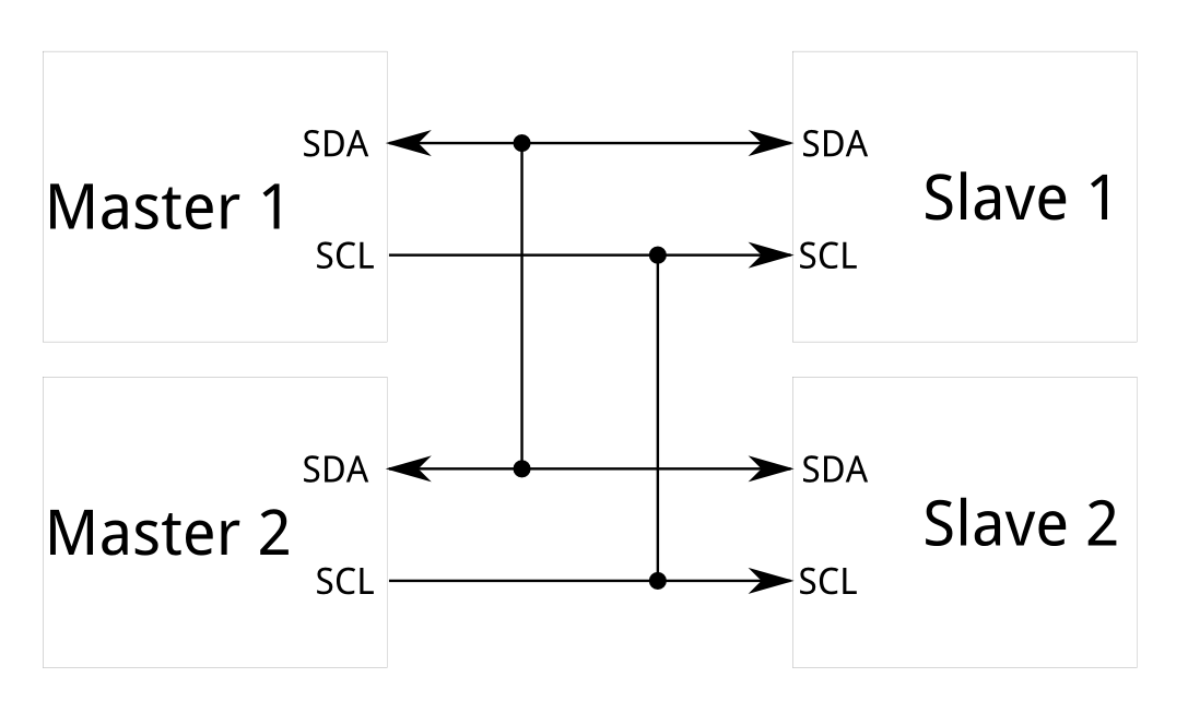
DS18B20 implements 1W (One Wire) interface and only requires one port pin for two way communication. Please note that 1W (One Wire) interface is not natively supported by Raspberry Pi that's why I had to connect DS18B20 via 1W (One Wire) to I2C bridge. I2C is one of interfaces natively supported by Raspberry Pi along with SPI interface. The Inter-integrated Circuit (I2C) Protocol is a protocol intended to allow multiple "slave" digital integrated circuits ("chips") to communicate with one or more "master" chips. Like the Serial Peripheral Interface (SPI), it is only intended for short distance communications within a single device. It only requires two signal wires to exchange information.

Please note that in this experiment we are going to use only one slave and Raspberry Pi will be a master.
Please find more info about I2C interface here: https://learn.sparkfun.com/tutorials/i2c
Please find DS18B20 spec here: https://datasheets.maximintegrated.com/en/ds/DS18B20.pdf
The communication with DS18B20 and Raspberry Pi will be via 1W (One Wire) to I2C bridge, DS2482-100. There're number of variations of this bridge with the newest one on the market being DS2482S-100+. Please find DS2482-100 spec here: https://www.maximintegrated.com/en/products/interface/controllers-expanders/DS2482-100.html
DS2482S-100+ (DS2482-100) I2C to 1-Wire Bridge


The bridge itself supports the communication but it must be soldered into interface module with appropriate electric circuit to work. For the sake of simplicity I decided to use a complete (already soldered) interface module and purchased one from here: http://netcruzer.com/im1wp-tbp.html
1-Wire Interface Module with I2C bus, 3.0V-5.5V, Pluggable TB (CODE: im1WP-TBP). Options: Header Type: 6.0mm Pin Header

Please note that you have to specify the length of pin headers and I selected the standard 6.0mm Pin Header option for my interface module so I can easily connect it to Raspberry Pi and DS18B20 using standard female-to-female jumper wires. This is how schematics of interface module looks like

This is how my setup looks like for temperature sensor. I'm going to use table lamp to heat up a temperature sensor simulating machinery overheating conditions. When overheating conditions are detected (>23C) LED will light up with red color indicating a problem.
Picture

If you prefer you can build electric circuit for interface module using DS2482-100 yourself however it is much easier to use already complete interface module. Please see below how it looks like (with DS2482-100 soldered in) comparing to a standalone DS2482S-100+
Front
|
Back
|
 |  |
Please review the following video to review the principle of how temperature is measured using DS18B20: http://1drv.ms/1M3VG8g
The slave address to which the DS2482-100 responds is shown in Figure below. The logic state at the address pins AD0 and AD1 determines the value of the address bits A0 and A1. The address pins allow the device to respond to one of four possible slave addresses. The slave address is part of the slave address/control byte. The last bit of the slave address/control byte (R/W) defines the data direction. When set to 0, subsequent data flows from master to slave (write access); when set to 1, data flows from slave to master (read access).
In my experiment A0 = 0 and A1 = 0 (first from 4 available slave addresses) so I2CTempAddress = 0x18 (001 1000)

Please note that in case you specify incorrect slave address when you run your app you will face an error "Slave address was not acknowledged."
The core functionality of the DS18B20 is its direct-to-digital temperature sensor. The resolution of the temperature sensor is user-configurable to 9, 10, 11, or 12 bits, corresponding to increments of 0.5°C, 0.25°C, 0.125°C, and 0.0625°C, respectively. The default resolution at power-up is 12-bit. The DS18B20 powers up in a low-power idle state. To initiate a temperature measurement and A-to-D conversion, the master must issue a Convert T [0x44] command. Following the conversion, the resulting thermal data is stored in the 2-byte temperature register in the scratchpad memory and the DS18B20 returns to its idle state.
The DS18B20 output temperature data is calibrated in degrees Celsius, for Fahrenheit applications a conversion formula must be used. The temperature data is stored as a 16-bit sign-extended two's complement number in the temperature register (see Figure below). The sign bits (S) indicate if the temperature is positive or negative: for positive numbers S = 0 and for negative numbers S = 1. If the DS18B20 is configured for 12-bit resolution, all bits in the temperature register will contain valid data. Table below gives examples of digital output data and the corresponding temperature reading for 12-bit resolution conversions.

Source code
using System;
using System.Collections.Generic;
using System.Linq;
using System.Text;
using System.Net.Http;
using Windows.ApplicationModel.Background;
using Windows.Devices.Gpio;
using Windows.System.Threading;
using System.Diagnostics;
using System.Threading.Tasks;
using AlexBackgroundApplication.ServiceReference1;
using Windows.Devices.Enumeration;
using Windows.Devices.I2c;
namespace AlexBackgroundApplication
{
public sealed class StartupTask : IBackgroundTask
{
BackgroundTaskDeferral deferral;
private GpioPin pinR, pinG, pinB;
private I2cDevice i2cTemp;
private const byte i2cTempAddress = 0x18;
byte[] ReadBuf;
byte[] WriteBuf;
double tempc = 0;
double tempf = 0;
public void Run(IBackgroundTaskInstance taskInstance)
{
deferral = taskInstance.GetDeferral();
Task t = InitI2C();
t.Wait();
DateTime startTime = DateTime.Now, endTime;
double elapsedMillisecs;
pinR = GpioController.GetDefault().OpenPin(13);
pinR.SetDriveMode(GpioPinDriveMode.Output);
pinG = GpioController.GetDefault().OpenPin(26);
pinG.SetDriveMode(GpioPinDriveMode.Output);
pinB = GpioController.GetDefault().OpenPin(16);
pinB.SetDriveMode(GpioPinDriveMode.Output);
pinR.Write(GpioPinValue.Low);
pinG.Write(GpioPinValue.High);
pinB.Write(GpioPinValue.Low);
while (true)
{
endTime = DateTime.Now;
elapsedMillisecs = ((TimeSpan)(endTime - startTime)).TotalMilliseconds;
if (elapsedMillisecs > 5000)
{
if (OWReset() == true)
{
OWWriteByte(0xCC);
OWWriteByte(0x44);
delay();
if (OWReadByte() != 0)
{
OWReset();
OWWriteByte(0xCC);
OWWriteByte(0xBE);
byte test = OWReadByte();
int testresult = (OWReadByte() << 8);
int result = test | testresult;
tempc = (result / 16.00);
tempf = ((1.80 * (result / 16.00)) + 32.00);
if (tempc > 23)
{
pinR.Write(GpioPinValue.High);
pinG.Write(GpioPinValue.Low);
pinB.Write(GpioPinValue.Low);
}
else
{
pinR.Write(GpioPinValue.Low);
pinG.Write(GpioPinValue.High);
pinB.Write(GpioPinValue.Low);
}
//Debug.WriteLine("C: " + tempc.ToString() + " ;F: " + tempf.ToString());
}
}
startTime = DateTime.Now;
}
}
}
private async Task InitI2C()
{
try
{
var settings = new I2cConnectionSettings(i2cTempAddress);
settings.BusSpeed = I2cBusSpeed.FastMode;
string aqs = I2cDevice.GetDeviceSelector();
var dis = await DeviceInformation.FindAllAsync(aqs);
i2cTemp = await I2cDevice.FromIdAsync(dis[0].Id, settings);
if (i2cTemp == null)
{
return;
}
}
catch (Exception ex)
{
throw new Exception("I2C Initialization Failed", ex);
}
}
private bool OWReset()
{
bool ret = true;
byte test;
ReadBuf = new byte[1];
WriteBuf = new byte[] { 0xB4 };
i2cTemp.WriteRead(WriteBuf, ReadBuf);
if (ReadBuf[0] == 0)
return false;
while (true)
{
i2cTemp.Read(ReadBuf);
test = Convert.ToByte(ReadBuf[0] | 0xFE);
if (test == 0xFE)
break;
}
i2cTemp.Read(ReadBuf);
test = Convert.ToByte(ReadBuf[0] | 0xFC);
if (test != 0xFE)
ret = false;
return ret;
}
private bool OWWriteByte(byte value)
{
bool ret = true;
byte[] buff = new byte[2];
byte test;
buff[0] = 0xE1;//setReadPointerCommand
buff[1] = 0xF0;//statusRegister
ReadBuf = new byte[1];
i2cTemp.WriteRead(buff, ReadBuf);
if (ReadBuf[0] == 0)
{
return false;
}
while (true)
{
i2cTemp.Read(ReadBuf);
test = Convert.ToByte(ReadBuf[0] | 0xFE);
if (test == 0xFE)
break;
}
buff[0] = 0xA5;//writeByteCommand
buff[1] = value;
ReadBuf = new byte[1];
i2cTemp.WriteRead(buff, ReadBuf);
if (ReadBuf[0] == 0)
{
return false;
}
while (true)
{
i2cTemp.Read(ReadBuf);
test = Convert.ToByte(ReadBuf[0] | 0xFE);
if (test == 0xFE)
break;
}
return ret;
}
private byte OWReadByte()
{
byte result = 0x00;
byte[] buff = new byte[2];
byte test;
bool error = false;
buff[0] = 0xE1;//setReadPointerCommand
buff[1] = 0xF0;//statusRegister
ReadBuf = new byte[1];
i2cTemp.WriteRead(buff, ReadBuf);
if (ReadBuf[0] == 0)
{
error = true;
}
if (error == false)
{
while (true)
{
i2cTemp.Read(ReadBuf);
test = Convert.ToByte(ReadBuf[0] | 0xFE);
if (test == 0xFE)
break;
}
ReadBuf = new byte[1];
WriteBuf = new byte[] { 0x96 };
i2cTemp.WriteRead(WriteBuf, ReadBuf);
if (ReadBuf[0] == 0)
{
error = true;
}
if (error == false)
{
buff[0] = 0xE1;//setReadPointerCommand
buff[1] = 0xE1;//readDataRegister
ReadBuf = new byte[1];
i2cTemp.WriteRead(buff, ReadBuf);
if (ReadBuf[0] == 0)
{
error = true;
}
if (error == false)
{
i2cTemp.Read(ReadBuf);
result = ReadBuf[0];
}
}
}
return result;
}
private void delay()
{
DateTime startTime = DateTime.Now, endTime;
double elapsedMillisecs;
while (true)
{
endTime = DateTime.Now;
elapsedMillisecs = ((TimeSpan)(endTime - startTime)).TotalMilliseconds;
if (elapsedMillisecs > 1000)
break;
}
}
}
}
|
Please note that the following commands were used in the code above
SKIP ROM [0xCC]
The master can use this command to address all devices on the bus simultaneously without sending out any ROM code information. For example, the master can make all DS18B20s on the bus perform simultaneous temperature conversions by issuing a Skip ROM command followed by a Convert T [0x44] command.
Note that the Read Scratchpad [0xBE] command can follow the Skip ROM command only if there is a single slave device on the bus. In this case, time is saved by allowing the master to read from the slave without sending the device's 64-bit ROM code. A Skip ROM command followed by a Read Scratchpad command will cause a data collision on the bus if there is more than one slave since multiple devices will attempt to transmit data simultaneously.
|
CONVERT T [0x44]
This command initiates a single temperature conversion. Following the conversion, the resulting thermal data is stored in the 2-byte temperature register in the scratchpad memory and the DS18B20 returns to its low-power idle state. If the device is being used in parasite power mode, within 10μs (max) after this command is issued the master must enable a strong pullup on the 1-Wire bus for the duration of the conversion (tCONV) as described in the Powering the DS18B20 section. If the DS18B20 is powered by an external supply, the master can issue read time slots after the Convert T command and the DS18B20 will respond by transmitting a 0 while the temperature conversion is in progress and a 1 when the conversion is done. In parasite power mode this notification technique cannot be used since the bus is pulled high by the strong pullup during the conversion.
|
READ SCRATCHPAD [0xBE]
This command allows the master to read the contents of the scratchpad. The data transfer starts with the least significant bit of byte 0 and continues through the scratchpad until the 9th byte (byte 8 – CRC) is read. The master may issue a reset to terminate reading at any time if only part of the scratchpad data is needed.
|
Connections
DS18B20
1W <-> DS2482-100 1W
PWR <-> +
GND <-> -
LED
GPIO(R) <-> GPIO13
GPIO(G) <-> GPIO26
GPIO(B) <-> GPIO16
GND <-> -
DS2482-100
GND <-> -
NC (Not connected)
VAUX (Not connected)
VCC <-> +
SDA <-> I2C1 SDA
SDL <-> I2C1 SDL
0V (5) (Not connected)
0V (4) (Not connected)
1W (3) <-> DS18B20 1W
V+ (2) (Not connected)
VX (1) (Not connected)
|

Vibration sensor

The main principle of shock switch is that conductive vibration spring and trigger pin are precisely placed in switch ontology and bond to curing position through adhesive. Normally the spring and the trigger pin don't contact, but once shook the spring will shake and contact with trigger pin to conduct and generate trigger signals.
Please see my setup for vibration sensor on the picture below. Please note that I used Lego Mindstorms EV3 large motor to generate a vibration.
Picture


Please review the following video to learn more about how I measured the level of mechanical vibration from the motor: http://1drv.ms/1M3VupJ. Please note that I placed vibration sensor close to the source of vibration.
Inside vibration sensor there's a switch that can break an electrical circuit, interrupting the current or diverting it from one conductor to another. In addition to switch it is required to have a pull-up resistor. In electronic logic circuits, a pull-up resistor is a resistor connected between a signal conductor and a positive power supply voltage to ensure that the signal will be a valid logic level if external devices are disconnected or high-impedance is introduced.
This is how it looks like schematically
<![if !vml]> <![endif]>
 <![endif]>
Please note that vibration sensor I used already has all necessary components (switch and pull-up resistor) embedded
Source code
using System;
using System.Collections.Generic;
using System.Linq;
using System.Text;
using System.Net.Http;
using Windows.ApplicationModel.Background;
using Windows.Devices.Gpio;
using Windows.System.Threading;
using System.Diagnostics;
using System.Threading.Tasks;
using AlexBackgroundApplication.ServiceReference1;
namespace AlexBackgroundApplication
{
public sealed class StartupTask : IBackgroundTask
{
BackgroundTaskDeferral deferral;
private GpioPin pinR, pinG, pinB;
private GpioPin pinPI;
bool found = false;
public void Run(IBackgroundTaskInstance taskInstance)
{
deferral = taskInstance.GetDeferral();
InitGPIO();
}
private void InitGPIO()
{
DateTime startTimeDelay = DateTime.Now, endTimeDelay;
double elapsedMillisecsDelay;
pinPI = GpioController.GetDefault().OpenPin(18);
pinPI.SetDriveMode(GpioPinDriveMode.Input);
pinR = GpioController.GetDefault().OpenPin(13);
pinR.SetDriveMode(GpioPinDriveMode.Output);
pinG = GpioController.GetDefault().OpenPin(26);
pinG.SetDriveMode(GpioPinDriveMode.Output);
pinB = GpioController.GetDefault().OpenPin(16);
pinB.SetDriveMode(GpioPinDriveMode.Output);
pinR.Write(GpioPinValue.High);
pinG.Write(GpioPinValue.Low);
pinB.Write(GpioPinValue.Low);
startTimeDelay = DateTime.Now;
while (true)
{
endTimeDelay = DateTime.Now;
elapsedMillisecsDelay = ((TimeSpan)(endTimeDelay - startTimeDelay)).TotalMilliseconds;
if (pinPI.Read() == GpioPinValue.Low)
{
found = true;
}
if (elapsedMillisecsDelay > 500)
{
if (found == true)
{
pinR.Write(GpioPinValue.Low);
pinG.Write(GpioPinValue.High);
pinB.Write(GpioPinValue.Low);
}
else
{
pinR.Write(GpioPinValue.High);
pinG.Write(GpioPinValue.Low);
pinB.Write(GpioPinValue.Low);
}
found = false;
startTimeDelay = DateTime.Now;
}
}
}
}
}
|
Connections
Shock switch
GND <-> -
PWR <-> +
GPIO <-> GPIO18
LED
GPIO(R) <-> GPIO13
GPIO(G) <-> GPIO26
GPIO(B) <-> GPIO16
GND <-> -
|

Photo interrupter

To put in simple photo interrupter consists of two parts: transmitter and receiver. Transmitter emits light and that light goes to receiver. If that light beam between transmitter and receiver is interrupted by some obstacles and receiver detects no incoming light even for a brief moment the output level will change.
Please see my setup for measuring RPMs with photo interrupter below
Picture


Please review the following video to learn more about how I measured RPM (Revolutions per minute) for a part driven by motor using photo interrupter: http://1drv.ms/1M3Vl5H. Please note that I attached a small piece of paper to the wheel which is rotated. When this small piece of paper passes through the gates of photo interrupter the sensor will generate interrupt, number of interrupts per minute will tell the speed of the motor.
Source code
using System;
using System.Collections.Generic;
using System.Linq;
using System.Text;
using System.Net.Http;
using Windows.ApplicationModel.Background;
using Windows.Devices.Gpio;
using Windows.System.Threading;
using System.Diagnostics;
using System.Threading.Tasks;
using AlexBackgroundApplication.ServiceReference1;
namespace AlexBackgroundApplication
{
public sealed class StartupTask : IBackgroundTask
{
BackgroundTaskDeferral deferral;
private GpioPin pinR, pinG, pinB;
private GpioPin pinPI;
public void Run(IBackgroundTaskInstance taskInstance)
{
deferral = taskInstance.GetDeferral();
InitGPIO();
}
private void InitGPIO()
{
DateTime startTimeDelay = DateTime.Now, endTimeDelay;
double elapsedMillisecsDelay;
bool found = false;
pinPI = GpioController.GetDefault().OpenPin(18);
pinPI.SetDriveMode(GpioPinDriveMode.Input);
pinR = GpioController.GetDefault().OpenPin(13);
pinR.SetDriveMode(GpioPinDriveMode.Output);
pinG = GpioController.GetDefault().OpenPin(26);
pinG.SetDriveMode(GpioPinDriveMode.Output);
pinB = GpioController.GetDefault().OpenPin(16);
pinB.SetDriveMode(GpioPinDriveMode.Output);
pinR.Write(GpioPinValue.High);
pinG.Write(GpioPinValue.Low);
pinB.Write(GpioPinValue.Low);
startTimeDelay = DateTime.Now;
while (true)
{
endTimeDelay = DateTime.Now;
elapsedMillisecsDelay = ((TimeSpan)(endTimeDelay - startTimeDelay)).TotalMilliseconds;
//if (elapsedMillisecsDelay > 1000)
{
if (pinPI.Read() == GpioPinValue.High)
{
pinR.Write(GpioPinValue.Low);
pinG.Write(GpioPinValue.High);
pinB.Write(GpioPinValue.Low);
}
else
{
pinR.Write(GpioPinValue.High);
pinG.Write(GpioPinValue.Low);
pinB.Write(GpioPinValue.Low);
}
startTimeDelay = DateTime.Now;
}
}
}
}
}
|
Connections
Photo interrupter
GPIO <-> GPIO18
PWR <-> +
GND <-> -
LED
GPIO(R) <-> GPIO13
GPIO(G) <-> GPIO26
GPIO(B) <-> GPIO16
GND <-> -
|

Button

The working principle is very simple when the button is pressed GPIO pin connected to the button will turn into a low level.
Please see my setup to simulate un/availability of machinery using a simple button switch below
Picture

Please review the following video to see how I simulated a power supply to an imaginary piece of equipment: http://1drv.ms/1M3VAxx
Source code
using System;
using System.Collections.Generic;
using System.Linq;
using System.Text;
using System.Net.Http;
using Windows.ApplicationModel.Background;
using Windows.Devices.Gpio;
using Windows.System.Threading;
using System.Diagnostics;
using System.Threading.Tasks;
using AlexBackgroundApplication.ServiceReference1;
namespace AlexBackgroundApplication
{
public sealed class StartupTask : IBackgroundTask
{
BackgroundTaskDeferral deferral;
private GpioPin pinR, pinG, pinB;
private GpioPin pinPI;
public void Run(IBackgroundTaskInstance taskInstance)
{
deferral = taskInstance.GetDeferral();
InitGPIO();
}
private void InitGPIO()
{
pinPI = GpioController.GetDefault().OpenPin(18);
pinPI.SetDriveMode(GpioPinDriveMode.Input);
pinR = GpioController.GetDefault().OpenPin(13);
pinR.SetDriveMode(GpioPinDriveMode.Output);
pinG = GpioController.GetDefault().OpenPin(26);
pinG.SetDriveMode(GpioPinDriveMode.Output);
pinB = GpioController.GetDefault().OpenPin(16);
pinB.SetDriveMode(GpioPinDriveMode.Output);
pinR.Write(GpioPinValue.High);
pinG.Write(GpioPinValue.Low);
pinB.Write(GpioPinValue.Low);
while (true)
{
if (pinPI.Read() == GpioPinValue.Low)
{
pinR.Write(GpioPinValue.Low);
pinG.Write(GpioPinValue.High);
pinB.Write(GpioPinValue.Low);
}
else
{
pinR.Write(GpioPinValue.High);
pinG.Write(GpioPinValue.Low);
pinB.Write(GpioPinValue.Low);
}
}
}
}
}
|
Connections
Button
GND <-> -
PWR <-> +
GPIO <-> GPIO18
LED
GPIO(R) <-> GPIO13
GPIO(G) <-> GPIO26
GPIO(B) <-> GPIO16
GND <-> -
|

Obstacle detection sensor

Obstacle detection sensor consists of infrared-transmitter, infrared-receiver and potentiometer. According to the reflecting character of an object if there's no obstacle emitted infrared ray will weaken with propagation distance and eventually disappear. If there's an obstacle when infrared ray encounters an obstacle it will be reflected back to infrared-receiver. Then infrared-receiver detects this signal and confirms an obstacle exists in front.
Please see below my setup with Lego Mindstorms EV3 robot (conveyor belt) to simulate a production line, I used obstacle detection sensor to count how many products are being produced on the production line
Picture

Please review the following video to see how I count products being produced on the production line: http://1drv.ms/1M3VKox
Source code
using System;
using System.Collections.Generic;
using System.Linq;
using System.Text;
using System.Net.Http;
using Windows.ApplicationModel.Background;
using Windows.Devices.Gpio;
using Windows.System.Threading;
using System.Diagnostics;
using System.Threading.Tasks;
using AlexBackgroundApplication.ServiceReference1;
namespace AlexBackgroundApplication
{
public sealed class StartupTask : IBackgroundTask
{
BackgroundTaskDeferral deferral;
private GpioPin pinR, pinG, pinB;
private GpioPin pinIRTIRR;
bool found = false;
public void Run(IBackgroundTaskInstance taskInstance)
{
deferral = taskInstance.GetDeferral();
InitGPIO();
}
private void InitGPIO()
{
DateTime startTime = DateTime.Now, endTime;
double elapsedMillisecs;
pinIRTIRR = GpioController.GetDefault().OpenPin(12);
pinIRTIRR.SetDriveMode(GpioPinDriveMode.Input);
pinR = GpioController.GetDefault().OpenPin(13);
pinR.SetDriveMode(GpioPinDriveMode.Output);
pinG = GpioController.GetDefault().OpenPin(26);
pinG.SetDriveMode(GpioPinDriveMode.Output);
pinB = GpioController.GetDefault().OpenPin(16);
pinB.SetDriveMode(GpioPinDriveMode.Output);
pinR.Write(GpioPinValue.High);
pinG.Write(GpioPinValue.Low);
pinB.Write(GpioPinValue.Low);
while (true)
{
endTime = DateTime.Now;
elapsedMillisecs = ((TimeSpan)(endTime - startTime)).TotalMilliseconds;
//if (elapsedMillisecs > 500)
{
if (pinIRTIRR.Read() == GpioPinValue.Low)
{
pinR.Write(GpioPinValue.Low);
pinG.Write(GpioPinValue.High);
pinB.Write(GpioPinValue.Low);
}
else
{
pinR.Write(GpioPinValue.High);
pinG.Write(GpioPinValue.Low);
pinB.Write(GpioPinValue.Low);
}
startTime = DateTime.Now;
}
}
}
}
}
|
Connections
Obstacle detection sensor
NULL (Not connected)
GPIO <-> GPIO12
PWR <-> +
GND <-> -
LED
GPIO(R) <-> GPIO13
GPIO(G) <-> GPIO26
GPIO(B) <-> GPIO16
GND <-> -
|

Here's a closer look at Lego Mindstorms EV3 robot (Moving conveyor belt)
Picture


For this scenario I used a simplified version of conveyor belt. In fact below is a picture of advanced conveyor belt I used in my other IoT demos. This robot has many more motors and sensors connected to it for various purposes

In order to control the robot I used an app written in C#.NET
App

For being able to control Lego Mindstorms EV3 robot via C#.NET I used Lego Mindstorms EV3 API available on github
NuGet packages
Here's the link to Lego Mindstorms EV3 API on github: https://github.com/BrianPeek/legoev3

Once you add appropriate NuGet packages corresponding references will be added to the project as shown below
References

Below is the source code of C#.NET to make conveyor belt constantly moving to carry products
Source code
using System;
using Windows.UI.Core;
using Windows.UI.Popups;
using Windows.UI.Xaml;
using Windows.UI.Xaml.Controls;
using Lego.Ev3.Core;
using Lego.Ev3.WinRT;
using AlexApp.Controls;
namespace AlexApp
{
public sealed partial class MainPage : Page
{
private Brick _brick;
private MotorControl _selectedMotorControl;
private SensorDataControl _selectedSensorControl;
private DateTime time1 = DateTime.Now, time2;
private TimeSpan diff;
public MainPage()
{
this.InitializeComponent();
ConnControl.Visibility = Visibility.Visible;
}
private async void TryToConnect(object sender, RoutedEventArgs e)
{
Overlay.Show("Connecting");
//ApplicationBar.IsVisible = false;
ConnControl.Visibility = Visibility.Visible;
var conType = CreateConnection();
await Dispatcher.RunAsync(CoreDispatcherPriority.Normal, async () =>
{
if (conType != null)
{
_brick = new Brick(conType, true);
_brick.BrickChanged += _brick_BrickChanged;
try
{
await _brick.ConnectAsync();
ConnControl.Visibility = Visibility.Collapsed;
ConnTypeRun.Text = ConnControl.GetConnectionType().ToString();
//ApplicationBar.IsVisible = true;
}
catch (Exception)
{
new MessageDialog("Could not connect", "Error").ShowAsync();
}
}
else
{
MessageDialog dialog = new MessageDialog("Invalid connection type for this device", "Error");
await dialog.ShowAsync();
}
Overlay.Hide();
});
}
private async void _brick_BrickChanged(object sender, BrickChangedEventArgs e)
{
MotorA.Update(_brick);
this.reportAsFinishedCycle();
}
private async void reportAsFinishedCycle()
{
time2 = DateTime.Now;
diff = time2 - time1;
if (diff.TotalSeconds > 1)
{
await _brick.DirectCommand.TurnMotorAtPowerForTimeAsync(OutputPort.A, 25, 0, 100, 0, false);
time1 = DateTime.Now;
}
}
private void MotorSettingClicked(object sender, RoutedEventArgs routedEventArgs)
{
var control = sender as MotorControl;
if (control != null)
{
MotorSettings.SaveSettings += MotorSettings_SaveSettings;
_selectedMotorControl = control;
MotorSettings.Show(
control.BrickInputPort,
_brick.Ports[control.BrickInputPort].Type,
control.MotorMovementType,
control.DegreeMovement,
control.PowerRatingMovement,
control.TimeToMoveInSeconds);
}
}
private void MotorSettings_SaveSettings(object sender, MotorSettingsEventArgs e)
{
if (_selectedMotorControl == null)
return;
MotorSettings.SaveSettings -= MotorSettings_SaveSettings;
_selectedMotorControl.MotorMovementType = e.MotorMovementType;
_selectedMotorControl.DegreeMovement = e.DegreeMovement;
_selectedMotorControl.PowerRatingMovement = e.PowerRatingMovement;
_selectedMotorControl.TimeToMoveInSeconds = e.TimeToMoveInSeconds;
_selectedMotorControl.UpdateUx();
_selectedMotorControl = null;
}
private async void MotorPlayClicked(object sender, RoutedEventArgs e)
{
var control = sender as MotorControl;
if (control != null)
{
var output = control.BrickOutputPort;
if (control.MotorMovementType == MotorMovementTypes.Degrees)
{
await _brick.DirectCommand.StepMotorAtPowerAsync(output, control.PowerRatingMovement, 0, (uint)control.DegreeMovement, 0, false);
}
else
{
if (control.TimeToMoveInSeconds == 0)
{
await _brick.DirectCommand.TurnMotorAtPowerAsync(output, control.PowerRatingMovement);
}
else
{
await _brick.DirectCommand.TurnMotorAtPowerForTimeAsync(output, control.PowerRatingMovement, 0, (uint)control.TimeToMoveInSeconds * 1000, 0, false);
}
}
}
}
private void SensorSettingClicked(object sender, RoutedEventArgs routedEventArgs)
{
var control = sender as SensorDataControl;
if (control != null)
{
SensorSettings.SaveSettings += SensorSettings_SaveSettings;
_selectedSensorControl = control;
SensorSettings.Show(
control.BrickInputPort,
_brick.Ports[control.BrickInputPort].Type,
_brick.Ports[control.BrickInputPort].Mode);
}
}
private void SensorSettings_SaveSettings(object sender, SensorSettingsEventArgs e)
{
if (_selectedSensorControl == null)
return;
SensorSettings.SaveSettings -= SensorSettings_SaveSettings;
_brick.Ports[_selectedSensorControl.BrickInputPort].SetMode(e.SensorMode);
_selectedSensorControl.UpdateUx();
_selectedSensorControl = null;
}
private ICommunication CreateConnection()
{
ICommunication returnType = null;
switch (ConnControl.GetConnectionType())
{
case ConnectionType.Usb:
returnType = new UsbCommunication();
break;
case ConnectionType.Bluetooth:
returnType = new BluetoothCommunication();
break;
case ConnectionType.WiFi:
returnType = new NetworkCommunication(ConnControl.GetIpAddress());
break;
}
return returnType;
}
}
}
|
Connections
Port A <-> Large Motor
Port B (Not connected)
Port C (Not connected)
Port D (Not connected)
Port 1 (Not connected)
Port 2 (Not connected)
Port 3 (Not connected)
Port 4 (Not connected)
|
Color recognition sensor

The TCS3200 programmable color light-to-frequency converter combines configurable silicon photodiodes and a current-to-frequency converter on a single monolithic CMOS integrated circuit. The output is a square wave (50% duty cycle) with frequency directly proportional to light intensity (irradiance).
Please find TCS3200 spec here: http://www.mouser.com/catalog/specsheets/TCS3200-E11.pdf
Please see my setup for color recognition sensor below. The idea is that, for example, we are supposed to produce red products, in fact products produced may be non-red (say blue) which will be considered a quality issue/defect. This way we can implement quality control process and count how many products were produced to spec and how many off spec
Picture


Please review the following video to learn how I used color recognition sensor to detect primary colors (RGB): http://1drv.ms/1M3VDth
The sensor works based on the theory of three primary colors. Therefore, knowing the proportion you can get the color of the tested object. For TCS3200, when a color filter is selected, it only allows a specific primary color to pass through and blocks the other two colors. For instance, when the red filter is selected, only the light of red color can pass through and that of green and blue is blocked. Thus, the value of red light can be obtained. Similarly the values of green and blue light are obtained. Then, based on the three values, the color of light reflected to the TCS3200 sensor can be analyzed. The TCS3200D sensor has 4 types of filter and the filter is selected based on the high/low of pin S2 and S3 on the module. Also, the output proportion of the four filters can be selected by S0 and S1, as 100%, 20%, 2%, or power down. The module is widely used in color digital camera, marine monitoring, atmospheric monitoring, color matching of color floor, etc.
The best distance between the TCS3200 and the tested object is 1cm. For color recognition we'll take a reading for each color sequentially. The reading with narrowest pulse width or highest frequency will be the major color.
Source code
using System;
using System.Collections.Generic;
using System.Linq;
using System.Text;
using System.Net.Http;
using Windows.ApplicationModel.Background;
using Windows.Devices.Gpio;
using Windows.System.Threading;
using System.Diagnostics;
using System.Threading.Tasks;
using AlexBackgroundApplication.ServiceReference1;
namespace AlexBackgroundApplication
{
public sealed class StartupTask : IBackgroundTask
{
BackgroundTaskDeferral deferral;
private GpioPin pinR, pinG, pinB;
private GpioPin pinOut;
private GpioPin pinS0, pinS1, pinS2, pinS3;
int colorNone, colorRed, colorGreen, colorBlue;
int colorNoneTotal, colorRedTotal, colorGreenTotal, colorBlueTotal;
string color = "None";
public void Run(IBackgroundTaskInstance taskInstance)
{
deferral = taskInstance.GetDeferral();
InitGPIO();
}
private int calcFrequency()
{
int result = 0;
bool found = false;
DateTime startTime = DateTime.Now, endTime;
double elapsedMillisecs = 0;
while (true)
{
if (pinOut.Read() == GpioPinValue.Low)
{
found = true;
}
else
{
if (found == true)
{
result++;
found = false;
}
}
if (elapsedMillisecs > 100)
break;
endTime = DateTime.Now;
elapsedMillisecs = ((TimeSpan)(endTime - startTime)).TotalMilliseconds;
}
return result;
}
private void InitGPIO()
{
DateTime startTime = DateTime.Now, endTime;
double elapsedMillisecs;
int count = 0;
pinOut = GpioController.GetDefault().OpenPin(27);
pinOut.SetDriveMode(GpioPinDriveMode.Input);
pinS0 = GpioController.GetDefault().OpenPin(18);
pinS0.SetDriveMode(GpioPinDriveMode.Output);
pinS1 = GpioController.GetDefault().OpenPin(23);
pinS1.SetDriveMode(GpioPinDriveMode.Output);
pinS2 = GpioController.GetDefault().OpenPin(24);
pinS2.SetDriveMode(GpioPinDriveMode.Output);
pinS3 = GpioController.GetDefault().OpenPin(25);
pinS3.SetDriveMode(GpioPinDriveMode.Output);
pinR = GpioController.GetDefault().OpenPin(13);
pinR.SetDriveMode(GpioPinDriveMode.Output);
pinG = GpioController.GetDefault().OpenPin(26);
pinG.SetDriveMode(GpioPinDriveMode.Output);
pinB = GpioController.GetDefault().OpenPin(16);
pinB.SetDriveMode(GpioPinDriveMode.Output);
pinS0.Write(GpioPinValue.High);
pinS1.Write(GpioPinValue.Low);
pinR.Write(GpioPinValue.Low);
pinG.Write(GpioPinValue.Low);
pinB.Write(GpioPinValue.Low);
while (true)
{
endTime = DateTime.Now;
elapsedMillisecs = ((TimeSpan)(endTime - startTime)).TotalMilliseconds;
if (elapsedMillisecs > 5000)
{
count = 0;
while (count < 10)
{
//Clear
pinS2.Write(GpioPinValue.High);
pinS3.Write(GpioPinValue.Low);
colorNone = calcFrequency();
//Red
pinS2.Write(GpioPinValue.Low);
pinS3.Write(GpioPinValue.Low);
colorRed = calcFrequency();
//Green
pinS2.Write(GpioPinValue.High);
pinS3.Write(GpioPinValue.High);
colorGreen = calcFrequency();
//Blue
pinS2.Write(GpioPinValue.Low);
pinS3.Write(GpioPinValue.High);
colorBlue = calcFrequency();
if (colorRed > colorGreen && colorRed > colorBlue)
{
colorRedTotal++;
}
else if (colorGreen > colorRed && colorGreen > colorBlue)
{
colorGreenTotal++;
}
else if (colorBlue > colorRed && colorBlue > colorGreen)
{
colorBlueTotal++;
}
else
{
colorNoneTotal++;
}
count++;
}
if (colorRedTotal > colorGreenTotal && colorRedTotal > colorBlueTotal)
{
color = "Red";
pinR.Write(GpioPinValue.High);
pinG.Write(GpioPinValue.Low);
pinB.Write(GpioPinValue.Low);
}
else if (colorGreenTotal > colorRedTotal && colorGreenTotal > colorBlueTotal)
{
color = "Green";
pinR.Write(GpioPinValue.Low);
pinG.Write(GpioPinValue.High);
pinB.Write(GpioPinValue.Low);
}
else if (colorBlueTotal > colorRedTotal && colorBlueTotal > colorGreenTotal)
{
color = "Blue";
pinR.Write(GpioPinValue.Low);
pinG.Write(GpioPinValue.Low);
pinB.Write(GpioPinValue.High);
}
else
{
color = "None";
pinR.Write(GpioPinValue.Low);
pinG.Write(GpioPinValue.Low);
pinB.Write(GpioPinValue.Low);
}
//Debug.WriteLine("R: " + colorRedTotal + " | G: " + colorGreenTotal + " | B: " + colorBlueTotal);
//Debug.WriteLine("Color: " + color);
count = 0;
colorNoneTotal = 0;
colorRedTotal = 0;
colorGreenTotal = 0;
colorBlueTotal = 0;
startTime = DateTime.Now;
}
}
}
}
}
|
Connections
TCS3200
S0 <-> GPIO18
S1 <-> GPIO23
S2 <-> GPIO24
S3 <-> GPIO25
LED (Not connected)
OUT <-> GPIO27
VCC <-> +
GND <-> -
LED
GPIO(R) <-> GPIO13
GPIO(G) <-> GPIO26
GPIO(B) <-> GPIO16
GND <-> -
|

This concludes this article!
Summary: In this walkthrough I illustrated how to use IoT devices to collect machinery health data and OEE data from the machinery. We also discussed the details of how sensors work, how to write sensor drivers and how you can control sensors programmatically on Raspberry Pi. In the next article I'm going to use the data collected in the context of preventative and predictive maintenance.
Tags: Microsoft Dynamics AX 2012 R3, Internet of Things, IoT, Windows 10 IoT Core, Visual Studio 2015, Background Application (IoT), X++, C#.NET, Drivers, Maintenance, OEE.
Note: This document is intended for information purposes only, presented as it is with no warranties from the author. This document may be updated with more content to better outline the issues and describe the solutions.
Disclaimer: Lego, Mindstorms, EV3 are trademarks and/or copyrights of the Lego Group.
Author: Alex Anikiev, PhD, MCP
Special thanks for collaboration in building this scenario goes to Lean Transformation Guru at MCAConnect, Phil Coy and Dynamics AX Manufacturing Expert at Microsoft, Steve Moses