Microsoft Dynamics AX 2012 Manufacturing – Lean IoT Scenario Part 2: Hardware/Device (Raspberry Pi)
Purpose: The purpose of this document is to illustrate how to make use of IoT device for a full automation of Make to Order Lean Manufacturing scenario in Microsoft Dynamics AX 2012.
Challenge: Microsoft Dynamics AX 2012 out-of-the-box enables mixed mode manufacturing including discrete, process, project and Lean approaches. In the previous part we established an end-to-end functional flow for Make to Order Lean Manufacturing scenario, this gives us a great context. Now the goal is to explore how we can make use of IoT device to implement a broader Lean IoT Demo scenario using the concept of "Intelligent" location.
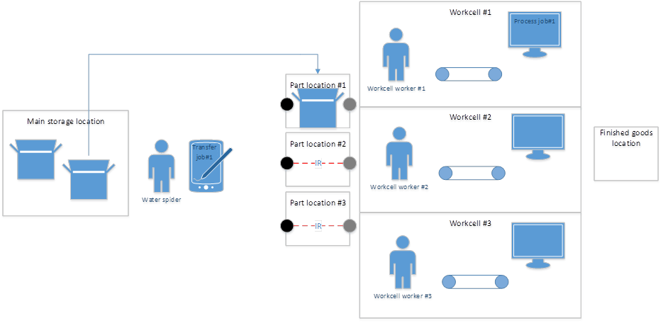
Solution: Lean IoT Demo scenario introduces a concept "Intelligent" location which is capable of monitoring itself and automatically send signals for ERP system to trigger appropriate actions. In the context of this scenario we have 2 people involved: Workcell worker and Water spider. Workcell worker is responsible for assembling the product in Workcell. Water spider is responsible for making sure that Workcell worker always has enough parts to produce the product. Workcell worker is constantly picking parts from his Parts location, and Water spider is replenishing Parts location from General storage location based on a need of Workcell worker. Now when demand comes in during Lean IoT Demo scenario we want "Intelligent" location to detect that it is empty and replenishment is needed, this will automatically trigger Transfer job for Water spider, and when Water spider replenished "Intelligent" location his Transfer job will automatically be completed because the location knows that it is full now. At this point "Intelligent" location will trigger Process job for Workcell worker, because now the location is full and Workcell worker can pick a part from it, once Workcell worker picks his part "Intelligent location" will automatically complete Process job and trigger another Transfer job for Water spider if there's a waiting demand. This cycle will be repeated over time while there's unsatisfied demand. This scenario showcases how operations efficiency can be tremendously improved when using the latest technological advancements. In its turn improved operations efficiency leads to more quality time spent manufacturing the product, more quality product itself and more happy customers in the end.
Please find Part 1 article of this series which describes a functionality here: http://ax2012manufacturing.blogspot.com/2015/09/microsoft-dynamics-ax-2012.html
Walkthrough
After we described the scenario verbally I'll also provide a visual diagram below
Diagram
<![if !vml]> <![endif]>
 <![endif]>
Having this scenario to implement we have to decide what hardware to use and how to use it. Obviously in order to implement "Intelligent" location which scans itself we'll need some sensors. In addition to this in order to support this scenario we need to decide what backend will be used and how, and how to write appropriate business logic for it. Finally we should not forget to think about how device will communicate with the backend, how device will be powered and how to observe the results of the scenario. This is exactly what we'll do below …
Let's start with the device itself
Section: Device
There may be multiple options of devices to be used. For example, Raspberry Pi 2 or Arduino. I chose Raspberry Pi 2 for this scenario. The Raspberry Pi is a tiny and affordable computer that you can use to learn programming through fun or any practical projects. Microsoft Windows Dev Center provides a tremendous amount of resources to get you started with building your own IoT scenarios. Here is a great place to start: https://dev.windows.com/en-us/iot
When looking at Raspberry Pi 2 device we'll see that it has got SD card (1) (where Windows 10 IoT Core OS will be loaded to), Ethernet port (2) for communication, HDMI port (3) for connecting to a display, power (4) and multiple USB ports( for example, if you want to connect an external USB keyboard, etc.)
Raspberry Pi

As I mentioned above I'm going to run Windows 10 IoT Core OS on Raspberry Pi 2 device. Assuming that you loaded Windows 10 IoT Core OS onto SD card, the OS will start right after you connect Raspberry Pi 2 to power. When OS will load and you connect Raspberry Pi to a display using HDMI port you will see the following user interface
Windows 10 IoT Core

In case you connect WiFi dongle to Raspberry Pi device you will also see a prompt to connect to available WiFi network(s) when OS loads
Please find detailed instructions about how to prepare Raspberry Pi device, load Windows 10 IoT Core OS on it and more here: https://dev.windows.com/en-us/iot
Okay, when we have Raspberry Pi device loaded with Windows 10 IoT Core OS we can take a closer look at its Pinout and figure out how to program it
Raspberry Pi Pinout

There's a number of Pins as described on the picture above. Different Pins have different meaning as described below
PWR Power
GND Ground
GPIO General Purpose Input/Output
SPI Serial Peripheral Interface
I2C Inter Integrated Circuit
|
Please find more details about Pinout here: https://ms-iot.github.io/content/en-US/win10/samples/Blinky.htm
Let's just clarify a couple of things about different types of Pins. There're a 3 main groups of Pins as described in the table below
GPIO – General Purpose Input/Output (represented by Windows.Devices.Gpio namespace)
GPIO is a generic pin on an integrated circuit whose behavior, including whether it is an input or output pin, can be controlled by the user at run time
- GPIO pins can be configured to be input or output
- GPIO pins can be enabled/disabled
- Input values are readable (typically high=1, low=0)
- Output values are writable/readable
- Input values can often be used as IRQs (typically for wakeup events)
|
SPI – Serial Peripheral Interface (represented by Windows.Devices.Spi namespace)
SPI bus is a synchronous serial communication interface specification used for short distance communication, primarily in embedded systems
|
I2C – Inter Integrated Circuit (represented by Windows.Devices.I2c namespace)
I2C is a multi-master, multi-slave, single-ended, serial computer bus which is typically used for attaching lower-speed peripheral ICs to processors and microcontrollers
|
Now we are at the point when we know enough about the device and can put something tangible together. Let's explore what sensors may help us to implement the scenario
Section: Sensors
This is how my setup for Lean IoT Demo scenario looks like
Setup

On my table you can observe the following components:
<![if !supportLists]>- <![endif]>Raspberry Pi device in the plastic case
<![if !supportLists]>- <![endif]>2 toy Wheels/Tires because this is what I'm going to put into Parts location
<![if !supportLists]>- <![endif]>LED/Light to indicate whether the location is empty (Red) or Full (Green)
<![if !supportLists]>- <![endif]>Obstacle detection sensor (lower left corner)
<![if !supportLists]>- <![endif]>Infrared transmitter sensor (upper right corner)
<![if !supportLists]>- <![endif]>Infrared receiver sensor (lower right corner)
The reason I have 3 sensors in place is because I actually implemented this scenario in 2 variations. Variation 1 uses Obstacle detection sensor which has both Infrared transmitter and Infrared receiver on-board, and Variation 2 uses Infrared transmitter sensor and Infrared receiver sensor separately. I'll explain the difference below
Here's a diagram that explains the details from hardware perspective
Diagram
<![if !vml]> <![endif]>
 <![endif]>
On the left hand side I describe the difference between Variation 1 and Variation 2 from signal propagation perspective.
Variation 1 uses Obstacle detection sensor which works like following:
<![if !supportLists]>- <![endif]>Infrared transmitter sends a signal
<![if !supportLists]>- <![endif]>Signal gets reflected from the object (assuming a part does exist in Part location)
<![if !supportLists]>- <![endif]>Infrared receiver receives reflected signal back within time period T
Variation 2 uses Infrared transmitter and Infrared receiver separately, Infrared transmitter is positioned directly against Infrared receiver, so this is how it works:
<![if !supportLists]>- <![endif]>Infrared transmitter sends a signal
<![if !supportLists]>- <![endif]>If there's nothing in between Infrared transmitter and Infrared receiver the latter will receive the signal within time period T
The principal difference between Variation 1 and Variation 2 is that for Obstacle detection sensor its Infrared transmitter and Infrared receiver already work in sync because they sit on the same board, and when you use them separately you have to physically control when and how the signal gets sent and when and how it gets received which is more work to do.
Obstacle detection sensor has great application for inventory counting (say products roll against it on a conveyor belt), however for an obstacle to be detected you have to physically move it against the sensor. This poses a slight inconvenience when "Intelligent" location has to detect its state (Empty or Full) right from the beginning of the scenario when you turn on the device. So the assumption would be that the location is Empty at the beginning (which may not be the case always). Actually that's why I also implemented the same scenario using Infrared transmitter and Infrared receiver separately, so I can control when and how the signal gets sent and received. And I can easily detect the initial state of the "Intelligent" location. This is a great example of why knowing the physical capabilities of your sensors is important for the success of the scenario. Please find more info about sensors I used here: http://sunfounder.com/
As you can see I connected my sensors with multiple jumper wires (female-to-female). In order to facilitate this you may consider using a HAT which plugs into Raspberry Pi and provides bus connections instead of using individual wires. Please find more info about Raspberry Pi HATs here: https://www.ghielectronics.com/catalog/category/538
Let's take a closer look at sensors
Sensors

Please review the following videos describing how hardware part of the scenario works:
<![if !supportLists]>- <![endif]>Using 1 sensor (Obstacle detection sensor) for "Intelligent" location monitoring: http://1drv.ms/1Q7E2mS
<![if !supportLists]>- <![endif]>Using 2 sensors (IR-T + IR-R) for "Intelligent" location monitoring: http://1drv.ms/1Q7E3av
Now we can think about how we can control Raspberry Pi device programmatically
Section: App
Luckily for us you can easily write Windows 10 Universal Apps with UI (user interface) or headless background apps without UI (user interface) for Raspberry Pi running Windows 10 IoT Core. Please find more info about how to start coding your IoT scenarios quickly here: https://ms-iot.github.io/content/en-US/win10/StartCoding.htm
In Part 3 article of this series I'll provide details about Headless Background App I wrote to program Raspberry Pi device, control and read the state of its sensors
Now let's put a quick word about the backend we will use for this scenario
Section: Backend
For this scenario in particular I used Microsoft Dynamics AX 2012 R3 deployed using Microsoft Dynamics Lifecycle Services (LCS): https://lcs.dynamics.com/. To enable communication with Microsoft Dynamics AX 2012 R3 I enabled IIS Web Services and exposed Inbound port via HTTP/HTTPS. I'll explain the details of the Web Services used for this scenario in Part 3 article of this series.
It is important to mention that when you build Windows 10 Universal Apps with UI (user interface) or headless background apps without UI (user interface) for Raspberry Pi running Windows 10 IoT Core you can easily add Web Service reference to your project just like you are used to. Then you can invoke Microsoft Dynamics AX 2012 R3 Web Service asynchronously (recommended) or synchronously from the App that runs on Raspberry Pi under Windows 10 IoT Core OS.
Please note that for the sake of simplicity I implemented a direct communication between Microsoft Dynamics AX 2012 R3 backend and Raspberry Pi App which is not suitable and would not scale for production deployment of solution.
Section: Hub
In order to provide a scalable and secure architecture for IoT devices communicating with Microsoft Dynamics AX 2012 R3 backend it would be recommended to use a middle-tier/hub, for example, Windows Azure Event Hubs which is a part of Windows Azure IoT Suite of services. Please find more info Windows Azure Event Hubs here: http://azure.microsoft.com/en-us/services/event-hubs/
Now let's think through the practicality of this setup
Section: Connectivity
In my setup I used Raspberry Pi Ethernet port to enable communication with Microsoft Dynamics AX 2012 R3 backend in the Cloud. Also it is possible to plug in a supported Raspberry Pi USB Wi-Fi Dongle for enabling wireless communication capabilities. When you load Windows 10 IoT Core OS the system will prompt you to connect to an available WiFi network. Then you can verify you connection details by going to Windows 10 IoT Core > Device settings > Network & Wi-Fi
Raspberry Pi USB Wi-Fi Dongle

Please note that I tried to use EDIMax WiFi Dongle with Raspberry Pi running Windows 10 IoT Core and it didn't work for me (as it was not listed as a supported WiFi Dongle for Windows 10 IoT Core OS at the time of this POC)
Please find more info about connecting Raspberry Pi to WiFi network here: https://www.raspberrypi.org/products/usb-wifi-dongle/, https://ms-iot.github.io/content/en-US/win10/SetupWiFi.htm, https://msdn.microsoft.com/nl-nl/library/windows/hardware/ff553642%28v=vs.85%29.aspx
Section: Power
Please note that you can connect Raspberry Pi to power using out of the box power adapter or external power adapter instead. Raspberry Pi will need a steady 2A for proper performance. External power adapter I used had the following characteristics:
Input: DC 5V-1000mA
Output: DC 5V-1000mA
Capacity: 2600mAh
Section: Display
As I mentioned before you can connect Raspberry Pi to a display using its HDMI port
Now as we explored the device I will also provide a quick reference about how IoT is helping companies to achieve better results today
Section: References
German Manufacturer Links Workers to Parts and Stations via RFID, Bluetooth
Bosch Rexroth developed the solution to improve efficiency and accuracy at its own hydraulic valve assembly facility, and is marketing the system for use by other manufacturers as well.
The solution sends instructions to each employee at his or her workstation, based on the components for the particular item being assembled at that location.
Please fine more info about how Bosch leverages IoT to achieve more here: http://www.rfidjournal.com/articles/view?13434
Summary: In this walkthrough I illustrated how to make use of IoT device for a full automation of Make to Order Lean Manufacturing scenario in Microsoft Dynamics AX 2012. We explored the details of the device, how to use sensors to implement the scenario, and then reviewed other considerations to help to establish a successful scenario. Now we should have a good understanding of hardware part and a solid foundation for taking care of software part.
Tags: Microsoft Dynamics AX 2012 R3, Internet of Things, IoT, Raspberry Pi, Windows 10 IoT Core, Windows 10 Universal Apps, Web Services.
Note: This document is intended for information purposes only, presented as it is with no warranties from the author. This document may be updated with more content to better outline the issues and describe the solutions.
Author: Alex Anikiev, PhD, MCP
Special thanks for collaboration in building this scenario goes to my colleague, Microsoft Dynamics AX Manufacturing expert, Dan Burke
Special thanks for collaboration in building this scenario goes to my colleague, Microsoft Dynamics AX Manufacturing expert, Dan Burke
Absolutely inspiring! Thank you!
ReplyDelete"• Nice and good article. It is very useful for me to learn and understand easily. Thanks for sharing your valuable information and time. Please keep updating IOT Online Training
ReplyDelete"
This comment has been removed by the author.
ReplyDeleteGet the instant solution for all technical issues which face by you Yeah! Because Now geek squad support 24x7 customers care always available for you. Only Dial geek squad support Number (+1)855-554-9777. And Our Geek Squad Team helps you As soon as possible.
ReplyDeleteHi Dear,
ReplyDeleteI really prefer your blog..! This blog are very useful for me and other. So I see it every day.
Check out For Business ERP services at Naviworld.com.sg Cloud ERP. This cloud ERP software and system helps to reduce your startup costs by avoiding upfront hardware and software purchases Microsoft ERP solutions. NaviWorld Singapore is your go-to vendor.
Visit Now - https://naviworld.com.sg/our-solutions/erp-cloud/
Thanks.